
01 · ENTER — Understand the work.
Follow one requirement from its source to the person who has to act on it. Read the project records, watch the review, and find where a correct answer becomes unusable. Bring the field conditions and the existing tools into that conversation.
Physical work adds constraints that a text corpus cannot capture alone: equipment, location, constructability, project state and accountable people. Name what is missing before building around the data that happens to be available.
02 · FRAME — Name the actual decision.
Choose one decision that needs to improve. Define the scope, the reviewer, the evidence they need and the action they can take. A request for a chatbot may need a requirement record, a review state and a report first.
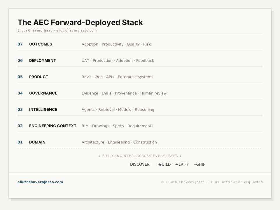
Place that decision in the workflow.
Select a layer for its role in the system.
03 · FORMALIZE — Make context and scope explicit.
Engineering requirements usually arrive as sentences. Software needs more: an entity type, a population, a property, an operator, a value, units, assumptions and a source. A threshold such as “all applicable elements must meet the stated condition” becomes a typed claim:
P = {x₁, x₂, …, xₙ}
∀x ∈ P, condition(x) = true
The first line defines what is in scope. The second defines what must hold. Getting the population right is usually harder than evaluating the predicate. If the population is too broad, the system reports false violations; if it is too narrow, it silently misses real ones. Formalization makes that choice visible and reviewable instead of allowing it to change implicitly between analysts.
The verification example in Selected Work makes this transformation concrete. It is deliberately synthetic: the point is not to pretend that one form can parse every requirement, but to show the seam where AI-assisted analysis should hand a structured claim to deterministic validation.
04 · INVESTIGATE — Search, connect and compare.
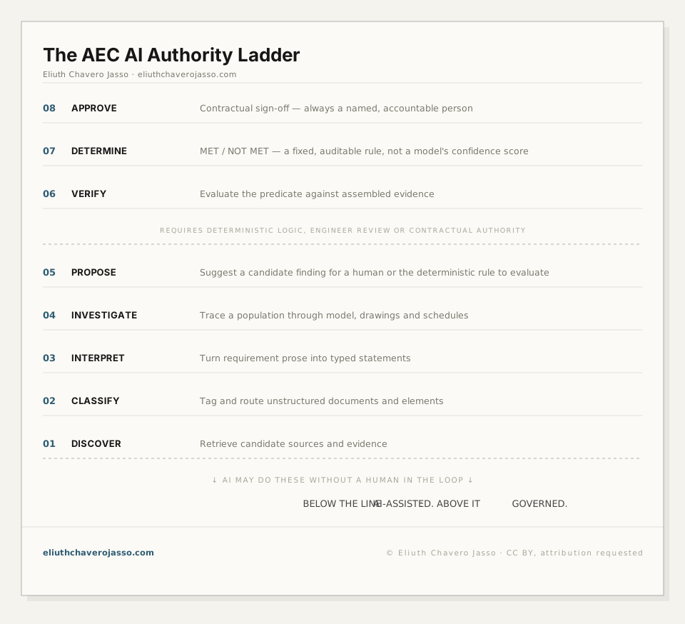
Give AI a bounded set of tools and the identity links between models, drawings and schedules. Let it choose the next useful source, record the observation and look for contrary evidence. An unanswered question stays visible.
Select a layer for its role in the system.
05 · VERIFY — Check what can be checked.
Confidence is not evidence. A determination becomes useful when it can point back to the drawing, schedule row, model element or field observation that supports it. The trace needs to survive after a project changes, a model is reloaded or the original conversation is no longer available.
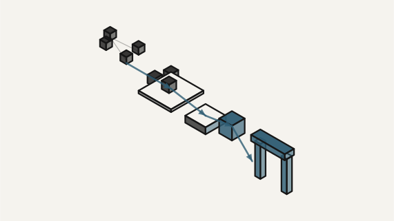
The evidence model is a graph because engineering facts are relational. A requirement scopes a population; a drawing informs a room; a room contains an element; a schedule gives that element a value; a predicate evaluates it; a counterexample drives the finding. Keeping those relations explicit lets a reviewer inspect the path rather than trust a paragraph generated at the end.
This synthetic example keeps the population, evidence and predicate visible. It is also the flow shown on Selected Work → Verification, where structured engineering data becomes a reviewable validation path. One explicit counterexample is more useful than an impression of risk because it tells the reviewer exactly what to inspect next.
06 · DEPLOY — Put the result into the working tool.
A result needs a place to go: the model, review workspace, issue or report. Preserve the evidence, rule and run that produced it. Validate installation, model state and the reviewer’s path through the software, alongside the check itself.
What it takes to survive the Revit host →
07 · LEARN — Observe what happened.
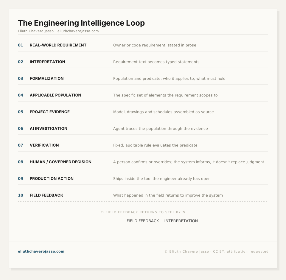
Did the reviewer understand the finding? Did the action resolve it? Did the next run change for the expected reason? Return those observations to the requirement, data model and tool boundary before adding another feature.
Technical appendix · Four lenses, one system
The same system can be read four ways: where each layer sits, who owns each decision, how action returns as feedback and how a source path becomes a reviewable determination.
Stack
Where context, intelligence, governance and deployment sit.
Jump to the Stack →Authority
What AI may assist with and where accountable judgment begins.
Jump to the boundary →Loop
How a result returns to the workflow as action and feedback.
Jump to the Loop →Graph → proof
How source relations become a formal, reviewable determination.
Jump to the evidence model →